

2014 News Release
Apr 01, 2014
The Industry's First* 4-Input/4-Output Switch Matrix IC for Satellite Broadcast TV Antennas

LAPIS Semiconductor Co., Ltd., a ROHM Group Company, has recently developed a 4-input/4-output switch matrix IC designed for satellite broadcast antennas.
The ML7405 is the first IC to feature a universal quad satellite broadcasting reception*2 circuit that connects two conventional 4-input/2-output switch ICs in parallel on a single chip.
The optimized, integrated design improves performance while enabling increased miniaturization and is expected to spur demand for satellite broadcast receivers.
Commonly used in areas such as Europe and South America, ‘universal’ satellite broadcast antennas are designed to receive four different frequencies and polarized waves from satellites. Typical models feature 1, 2, or 4 outputs. However, there is a growing demand for 4-output types, since at least four outputs are required receive or record four satellite broadcasts at the same time. This type of universal ‘quad-satellite’ broadcast antenna is expected to spread to North America, India, Middle East or Africa, where broadcast satellites will be launched in the near future.
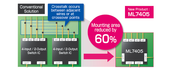
Previously, two conventional 4-input/2-output switch ICs were connected in parallel in order to support universal quad-satellite broadcast antennas featuring 4 outputs. But this can become problematic in high-frequency circuits since board layout and component wiring can have a significant effect on performance and characteristics, and mounting two switch ICs requires longer circuit wiring – possibly resulting in larger signal loss and crosstalk*3 (due to coupling between wires). Until now, this inherent drawback presented a major obstacle to widespread adoption of universal quad-satellite broadcast antennas.
Terminology
- *1 : Satellite broadcast receiver circuit
- A receiver attached to a satellite broadcast antenna that amplifies weak radio waves from satellites and converts them into the intermediate-frequency range.
Also referred to as an LNB (Low Noise Block).
- A receiver attached to a satellite broadcast antenna that amplifies weak radio waves from satellites and converts them into the intermediate-frequency range.
- *2 : Universal quad satellite broadcast receiver antenna
- A satellite broadcast receiver designed to receive four types of broadcasts in different frequencies and polarizations. This type of receiver, which is currently available in Europe and South America, is expected to expand to other regions such as India and Africa where broadcast satellites will be launched in the near future.
Satellite receivers eliminate the need for terrestrial broadcast equipment, making it possible to watch a variety of TV content in areas where it is difficult or impossible to receive conventional reception.
- A satellite broadcast receiver designed to receive four types of broadcasts in different frequencies and polarizations. This type of receiver, which is currently available in Europe and South America, is expected to expand to other regions such as India and Africa where broadcast satellites will be launched in the near future.
- *3 : Crosstalk
- Unwanted signal leakage, which becomes larger at high frequencies due to electromagnetic coupling between components and/or wires.
Key Advantages
- The industry's first 4-input/4-output switch matrix IC for satellite broadcast antennas
- The novel design integrates all required switch circuitry for universal quad-satellite broadcast antennas in a single IC, preventing both signal loss and crosstalk that occur when using two conventional 4-input/2-output switch ICs.
This not only facilitates the development and manufacture of universal quad-satellite broadcast antennas, but reduces mounting area by approximately 60%.
- Achieves low crosstalk equivalent or better than 4-input/2-output switch ICs
- A wide frequency range (950MHz-2150MHz) is required for satellite broadcasting reception, and incorporating 4-input/4-output switch capability on a single chip will normally increase crosstalk between internal components and wiring within the IC itself. However, through a unique circuit design and optimized layout LAPIS Semiconductor was able to achieve 25dB isolation with low crosstalk equivalent to or better than conventional 4-input/2-output switch ICs.
- Perfect impedance matching
- Impedance mismatches between input/output elements in high-frequency circuits may lead to problems such as reflected loss and/or undesired radio wave emissions.
Connecting two conventional 4-input/2-output switch ICs in parallel will result in an impedance of 25Ω, causing a mismatch in most high-frequency circuits where the input/output impedance is normally 50Ω.
In contrast, this new IC integrates two conventional switch ICs into one, maintaining an impedance of 50Ω.
This prevents impedance mismatching, simplifying board design.
Features
- Provides IF signal switching for universal quad satellite broadcast antennas on
a single chip
- Proprietary high-frequency circuit design technology utilized to reduce loss
and minimize crosstalk
- Low power consumption
Applications
- Satellite broadcast antennas/high-frequency signal switches
Sales Plan
- Package
- 32pin WQFN
- Sample Shipment
- Already started
- Mass Production
- From February 2014
Contact
For customers' inquiry regarding this release: please go to ![]() the inquiry page
the inquiry page
* Information in the press releases is current on the date of the press announcement, but is subject to change without prior notice.
*Please note that the names of companies and products described in this document are the trademarks or registered trademarks
of their respective companies and organizations.
